Shadow Art with Unity

A few days ago I saw video titled Shadow art is better with Legos 

Watching this video got me thinking about how something like this could be done and started to look for more information on what this was all about.

I was interested in seeing what other possibilities for Shadow Art were available and found some interesting ideas.

That’s only a subset of what can be described as Shadow Art!

The way I understood it, was that you could arrange shapes in multiple ways to block the light and end up with a shadow that created a familiar shape.

The great thing about programming is that, usually, you can take an idea and turn that into some sort of demo! Even better when graphics are involved 😉

So, I decided to go ahead and make a demo that would result in some sort of Shadow Art!

Using Unity allowed me to focus on the core of the problem rather than going out and solving all sorts of dependencies that the idea depended on.
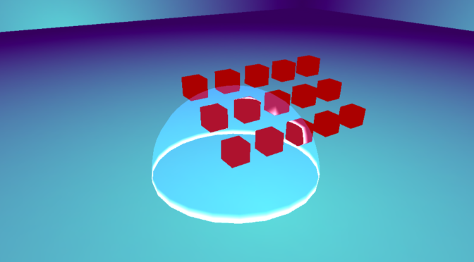
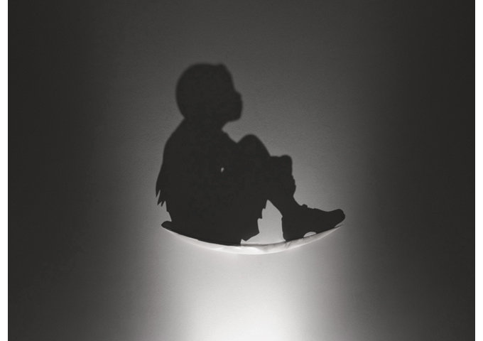
Here’s the result:

shadow_art

Thank’s to Unity’s WebGL export capabilities I’ve put up a runnable version of this code:

Shadow Art with Unity Demo, check it out!

launch_demo
Launch the Demo!


Here’s a more technical explanation of how this was achieved
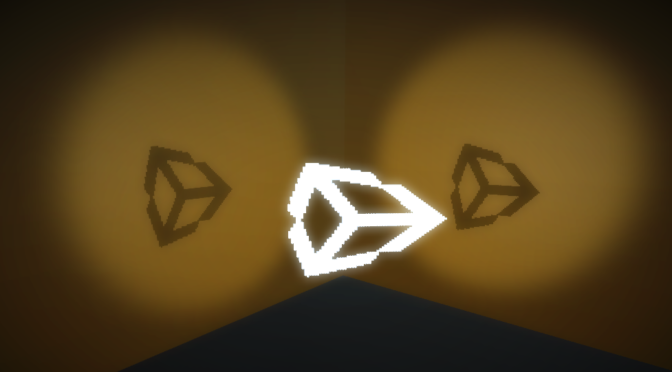
The setup

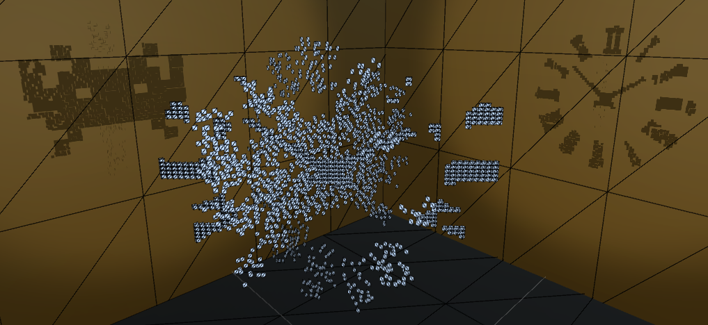
I went for having 2 spot lights set up, to project the shadows

two_spotlights

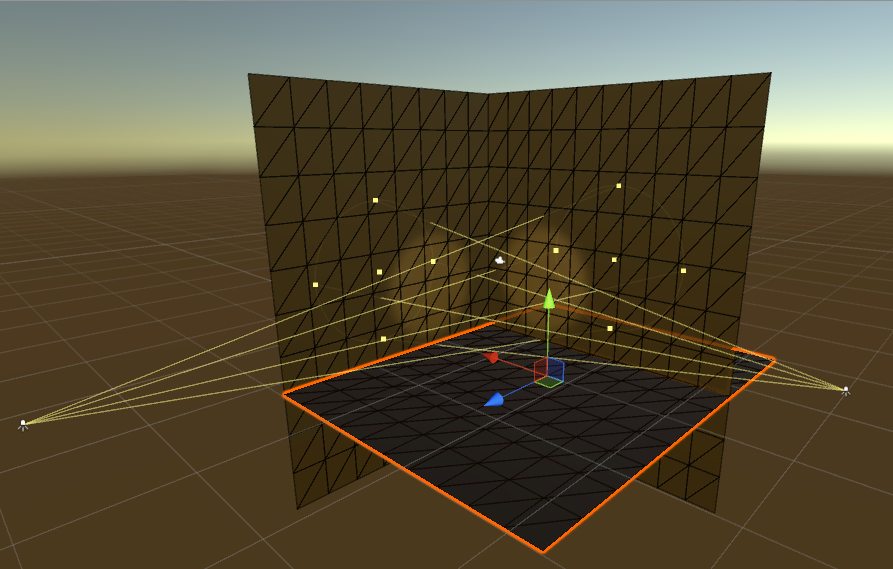
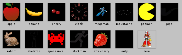
Then have a number of textures that are used to create the geometry

textures_shadow_art

Since there are 2 spotlights, I wanted to see if 2 separate shadows could be generated from the same mesh, similar to what was being done on the video shown for the Magical Angle Sculptures, except I went for just 2 shadows instead of 3!

combined_mesh
The resulting mesh

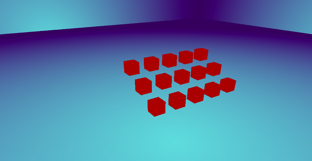
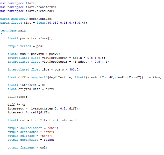
The way this is computed is in 3 passes:
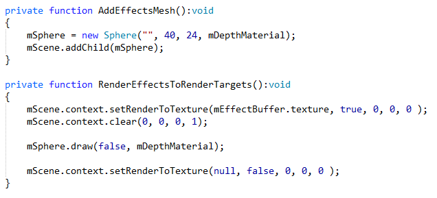
First Pass

This is the most important step, since it is here where the overlap is calculated and sets up the base for showing 2 shadows at the same time.

To figure out the overlap:

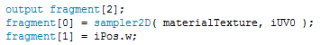
  1. Iterate through the pixels on one of the textures
  2. As soon as there’s an opaque pixel do a look up on the other texture
  3. If the lookup results in a pixel that’s also opaque, then generate the vertices for a cube at that position (x,y) and then center the z position
  4. Lastly, the overlapping pixel is stored so that it is not accessed again
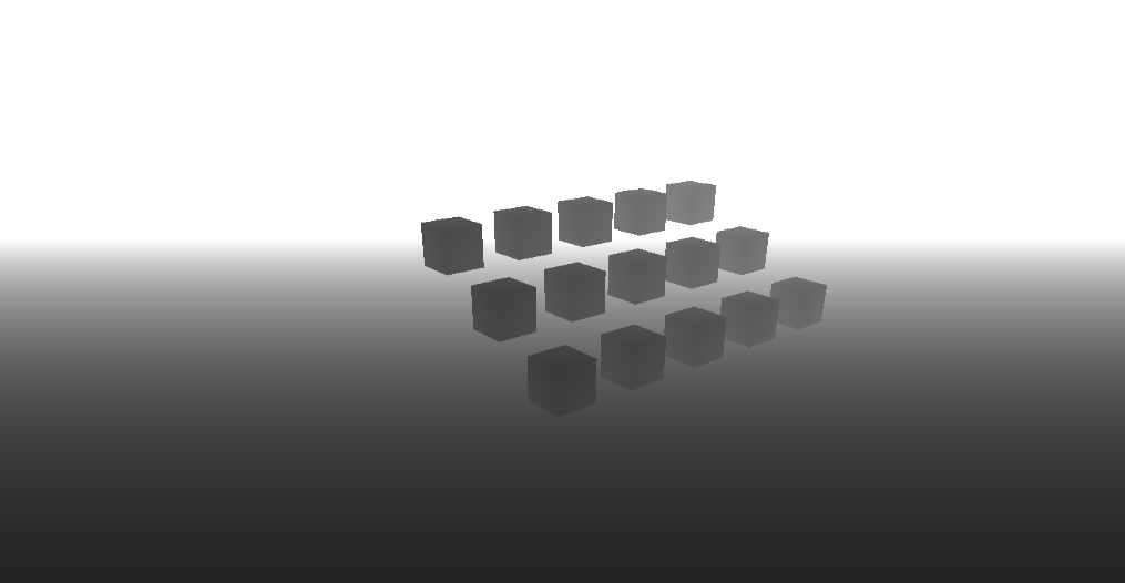
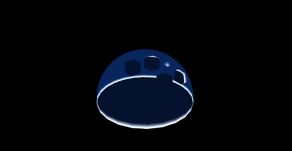
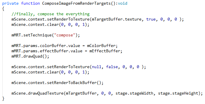
Second & Third Pass

These are more generic, and essentially create geometry for opaque pixels where geometry hasn’t been created before.

To give it a less uniform feel, there’s a random depth value applied to each new piece of geometry.
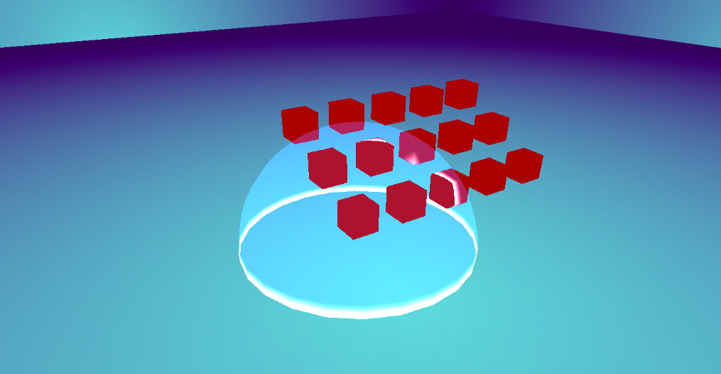
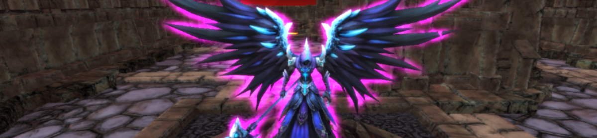
Image Effects

Unity comes with a number of pre-built Image Effects which helped to make this look more presentable.

I’m using the Vignette and Bloom Image Effects to create the final look for the presentation. You can see how adding them up looks below.

shadow_art_image_effects

Hope you find this fun to play around with, and if you have some cool ideas let me know!

And remember, you can always follow me on twitter @JavDev

Multiple render targets and Stage3D

For some time I’ve been curious on how to do things with the depth buffer using Stage3D.

As far as I could find, there is no real “direct” way to access the depth buffer with Stage3D, so I went ahead and did the next best thing, which was to build my own Depth Buffer in a shader.

I saw that this could be done thanks to Flare3D’s MRT demo and started learning how I could use this to test out some things I’ve been thinking about.

depth_01

color_01

Now that I had a depth buffer in place, the next step was to use this to see what sort of techniques I could combine it with.

I’ve been following Dan Moran on Patreon  and decided to try out an intersection highlight shader which he describes in one of his videos. This looked fun to do, so I went ahead and tried to implement a basic form of it using Flare3D’s shading language FLSL.

intersection_shader

Here’s how the shader turned out:

shader

You can also get it from here

The way that this shader works is in the following:

  1. Provide a texture with depth information
  2. Check if the difference between your current position and the value on the depth buffer is within a threshold
    1. If it is within the threshold, then use the smoothStep function to create a sort of “fall-off” effect, which at the maximum value makes the color white, and if not it fades out into the color of your mesh (or the tint being applied to it)
  3. One more thing to keep in mind is that you need to use screen space coordinates so that you test against the texture’s UVs and your own position

There are some more things to consider, such as the color format of your depth texture. If you use regular 32 bit RGBA values, then you will get some banding since the data in depth texture won’t be as precise as you need it, so using an RGBA_HALF_FLOAT value is recommended.

The final part comes by composing the 2 buffers together to create the final image. This is achieved by performing additive blending of the 2 render targets using another shader that outputs it to a final 3rd render target, which is then drawn on screen.

color_02

+

effect_01

=

composed_01

But, in practice how is this all achieved?

  1. Render all the geometry that you don’t want to use for effects together to a render target
    1. Also, use the MRT technique to be able to export a 2nd texture which is the equivalent of your depth buffer
    2. mrt_output
  2. Render your effect meshes to another render target and supply the depth texture as a parameter
    1. effect_mesh
  3. Finally, take the outputs of steps 1 & 2, and place them into a 3rd shader that does the additive blending for you and “composes” the final image for your shader.
    1. compose_material
  4. Draw a full screen quad with your final composed image!

Using Intel GPA you can see how the Render Targets all look:

In this case, you are only drawing what you need once to a number of buffers, and in the end compositing an image from all the various steps.

I’ve created a repo on GitHub that you can download and check out and hopefully extend for your own needs 🙂

You can also follow me on @jav_dev