3D Printing your game code

A while ago I heard that Shapeways launched a format called SVX that allowed for the exporting of voxel geometry to an intermediate format. This format could then be uploaded to their servers and they would then convert it to something that could be 3D printed!

This sounded like it would be a lot of fun to investigate, so I started looking at their format so that I could go ahead with some of the ideas I had.

The format is pretty straight forward, as it says that if there is a voxel occupying a region, it should be marked as white on a white & black image (PNG).

Enter

web_logo_384

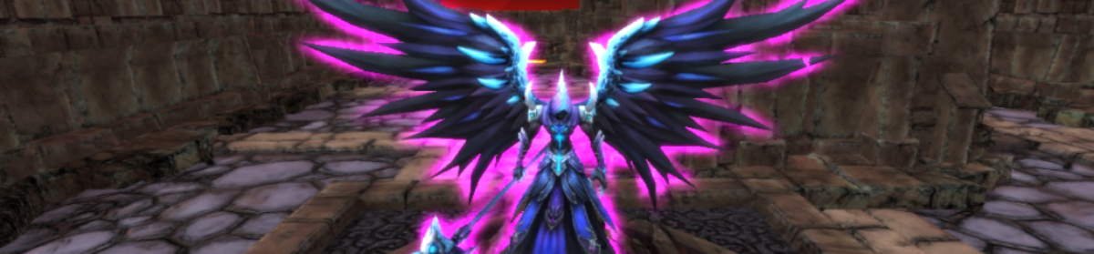
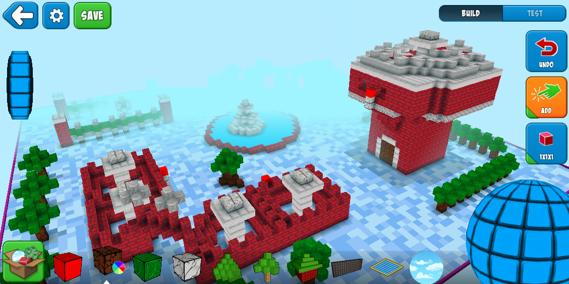
So, for the last 2 years I’ve been part of a team working on a game that lets users create all sorts of whacky levels, using blocks. Not only that, but we’ve had real time multiplayer from the start and we’ve also allowed you to customize your avatar, so pretty much everything in the game is user generated content.

We’ve had a number of releases, and at one point we had a level with Bots in it, where you would go in and see how long you could survive after BLASTING endless waves of bots!

Seeing how this was the most played level at the time, I thought it would be great to use that as my go-to model for my little 3D printing experiment.

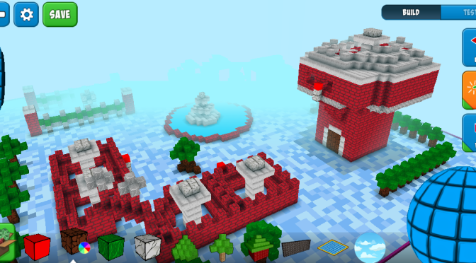
This is what the level looks like now:
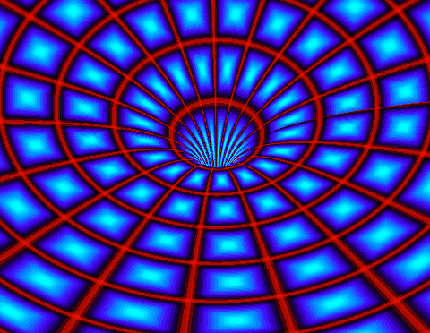
world_01

The SVX format

The idea of the SVX is quite simple, since it just wants you to mark a block as occupied by placing a white color, like so:

slice_8

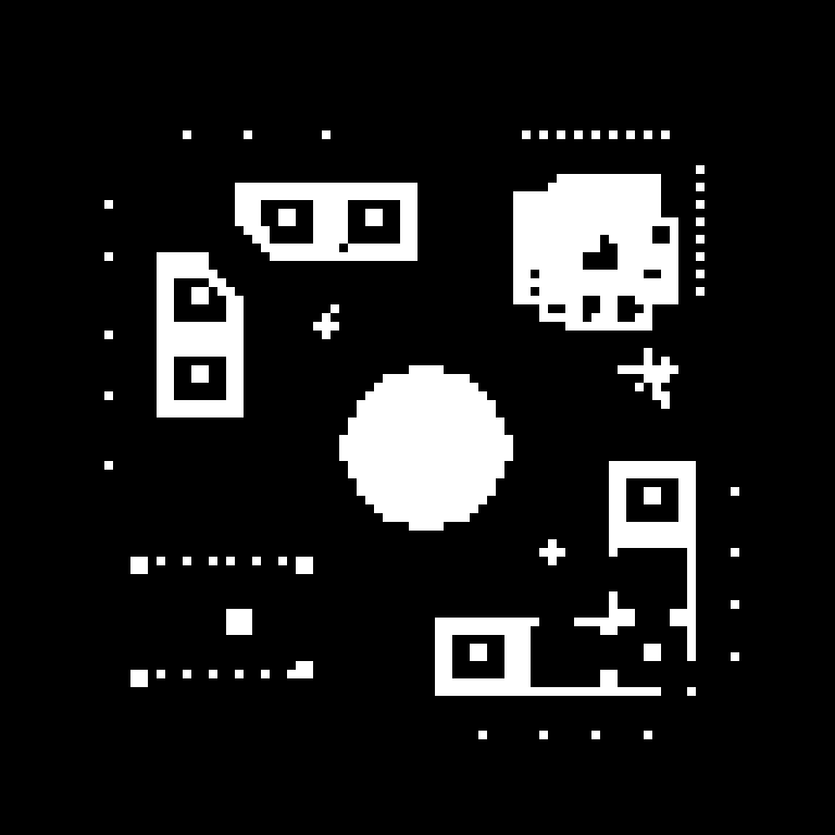
This would be the top down view of the bot level (notice the fountain in the center?)

However, there are a few things that I learned while doing this:

  1. Base: I need to have a base, just placing these pieces on the bottom most layer won’t work as there’s nothing they’re attached to (i.e. the structures would be floating)
  2. Distance: Shapeways has a smoothing algorithm that will make things really smooth, but if the voxels are placed too close together, they will smooth out a bit too much, making a block look like a cone, for example, so for every block I added 8 blocks on the SVX file!
  3. Loose Shells: There’s a final step to the process which detects something called loose shells. This is basically to ensure that there are no floating pieces in a level.
    1. This makes it quite hard to take just any level since everything has to be connected, and at times the insides of structures are not connected since we allow free-form level creation.
    2. Fortunately, the Shapeways model editor tells you exactly where the loose shells are, so its only a matter of editing your level a little bit and you got no more loose shells!

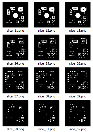
This is part of what the files I used for the model look like:

slices

Once I uploaded the collection of files to Shapeways, I ended up with this model:

side_view

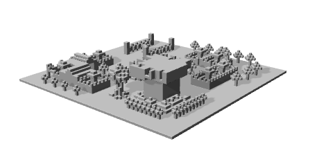
Now, it was just a matter of getting it printed and delivered.

It was an awesome moment when I finally got a 3D Printed version of the code that I’d been writing together with my team for such a long time!

The finished piece

IMG_4037 IMG_4036

If you’re interested, you can check out the level here, and even get a copy of it printed:

  1. RoboBlastPlanet Bot Level

You can also check out other cool stuff that they have in Shapeways, which helped to inspire me to make this 3D print!

You can also follow me on Twitter on @JavDevGames!

WebGL and shaders

Though I’ve heard about ShaderToy for a while, and looked at various examples of what they do, I never really had spent much time trying it out.

I recently started looking into Javascript and ThreeJS and very shortly the idea of making a cool background animation came into mind.

I wanted to do a copy of the PlayStation3’s background menu, but didn’t find much about it online. I ended up going to ShaderToy and doing my own, based off of another shader:

I think it came out pretty well, and made it using ShaderToy. Now I’ve managed to port it over to ThreeJS:

XBM Shader

How does this work?

Main Function #1

The meat of the work is done in the fragment shader.

[code language=”javascript”]

color += calcSine(uv, 0.20, 0.2, 0.0, 0.5, vec3(0.5, 0.5, 0.5), 0.1, 15.0,false);,
color += calcSine(uv, 0.40, 0.15, 0.0, 0.5, vec3(0.5, 0.5, 0.5), 0.1, 17.0,false);,
color += calcSine(uv, 0.60, 0.15, 0.0, 0.5, vec3(0.5, 0.5, 0.5), 0.05, 23.0,false);,

[/code]

The main function calls into calcSine. Every call to calcSine() creates a new “line” in the shader.

Calc Sine

The calcSine() function, simply calculates the value to pass into the sin() function, and is multiplied by various parameters (amplitude & offset). Amplitude meaning how much to stretch the values by in the y-axis, and offset moving it that much of the screen percentage up (5%, 10%, etc.)

[code language=”javascript”]

float angle = time * speed * frequency + (shift + uv.x) * 3.14;

[/code]

The next trick is to set a sort of exit criteria, which is diffY. What this asks is how far the value we got from sin() is from our current uv.y value. This is important since it determines if we’re below or above the uv.y coordinate we’re calculating this for.

dSqr simply figures out how far we are from the uv.y coordinate

[code language=”javascript”]

float y = sin(angle) * amplitude + offset;,
float diffY = y – uv.y;,
float dsqr = distance(y,uv.y);

[/code]

The if-statement I put in there is done to determine if we’re below or above, and how to handle it. Multiplying dSqr by 8.0 helps to make the cut off more smooth than multiplying by something higher. Multiplying by 12 would create a more cutting effect,  while multiplying by something below it makes the image more blurry.

[code language=”javascript”]

if(dir && diffY > 0.0)
{
dsqr = dsqr * 8.0;
}
else if(!dir && diffY < 0.0)
{
dsqr = dsqr * 8.0;
}

[/code]

The last step is to apply a power function & smoothstep to make the final effect and cause that “fadeout” effect around the lines.

[code language=”javascript”]

scale = pow(smoothstep(width * widthFactor, 0.0, dsqr), exponent);

[/code]

Main Function #2

What calling calcSine() multiple times allows us to do is to shift the color being returned up closer to white. This creates an effect of almost having “additive” blending, and makes the faded-out regions shiny brighter when they overlap.

At the end of the main function, a final step is done to tint the entire background with a color, and make this into a gradient color.

[code language=”javascript”]

color.x += t1 * (1.0-uv.y);
color.y += t2 * (1.0-uv.y);

gl_FragColor = vec4(color,1.0);

[/code]

Putting all this together, and updating the “time” uniform value finally gives us the final effect.

I’ve uploaded the sample to GitHub as well, so have a look there!

Wormhole effect in flash

A few years ago I started attempting to learn some of the stuff that the demoscene guys do. I did a little test with a wormhole effect that I’d seen in a number of demos, but nobody had really done a flash version (or at least my google-fu was not good enough to find one). So, I went ahead and implemented it. Here it is below:

Click on the images to switch the bitmap being applied to it
Press left/right on your keyboard to spin the wormhole around!

If you’d like to see more on how this effect is made, check out this website:

Creating Demos – Coder Tutorial #3 [Movement without Motion]